Rundown Tank (런다운 탱크)는 Lube Oil System의 최 상부에 위치하고 있으며, 비상 상황 발생시 (Lube Oil Pump Trip 혹은 Steam 공급 중단 등) Compressor 등에 Lube Oil이 공급 안될 경우를 대비해 설치한다.
Lube Oil 공급이 갑자기 중단될 경우 Compressor 등의 회전기기 베어링이 과열로 인한 손상을 입을 수 있어, 기계가 안전하게 정지할 수 있도록 Coast Down 시간 동안 (최소 3분) Lube Oil을 베어링에 수두압으로 공급 하는 역할을 한다.
API 614 Lubrication, Shaft-sealing and Oil-control Systems and Auxiliaries
Part 2: Special-purpose oil systems
4.9.2 Lube-oil rundown tanks
4.9.2.1 If specified, a separately mounted emergency lube-oil rundown tank (either atmospheric or pressurized) shall provide oil for the coast-down period specified by the purchaser. This tank shall be sized for not less than 3 min of normal operating lube-oil flow (see Figures B.15 and B.16). Unless otherwise specified, the tank shall be made of austenitic stainless steel.
Coast-down time shall be provided by the purchaser (normally the supplier of the equipment served by the oil system).
NOTE : The minimum sizing criteria results in more than 3 min of coast-down oil flow due to supply pressure decay.
4.9.2.2 A rundown tank shall be provided with a sight flow glass in the tank overflow line. The sight flow glass shall be located in an area that can be readily observed, such as the oil reservoir or equipment operating deck. A DN 150 (NPS 6) nozzle for accessing and inspecting the interior of the rundown tank shall be provided. Alternatively, for atmospheric rundown tanks, a bolted cover can be provided in lieu of the DN 150 (NPS 6) nozzle for access and inspection. The vendor shall specify the allowable minimum and maximum height of the bottom outlet nozzle above the machine centreline; the maximum static head shall be less than the lube-oil trip pressure but not less than 30 kPa (0,3 bar; 5 psig) at the beginning of coast-down.
4.9.2.3 When an atmospheric rundown tank is provided in accordance with Figure B.15, it shall be provided with low-level alarm and high-level permissive start functions. These functions may be served by a common device.
4.9.2.4 A pressurized tank (see Figure B.16) shall be designed in accordance with the specified pressure design code and, if specified, shall be code stamped. NOTE Code stamping might not be applicable for pressure design codes other than ASME.

1 drilled check valve
2 lube-oil supply
3 to equipment
4 to reservoir or drain header
5 low-level alarm
6 permissive start
a Figure B.15, option A: The purchaser may specify an atmospheric breather valve.
b This tank shall be located at an elevation such that the static head is less than the equipment lube-oil trip pressure.
c This valve is normally closed; it is opened only to fill the tank before the equipment is started. Figure B.15, option B: This valve may be solenoid-controlled to allow an automated start.
d To reduce pressure-line losses, locate and design interconnecting piping as per system designer's recommendations.
e Sight glass should be located near the reservoir in a visible location.
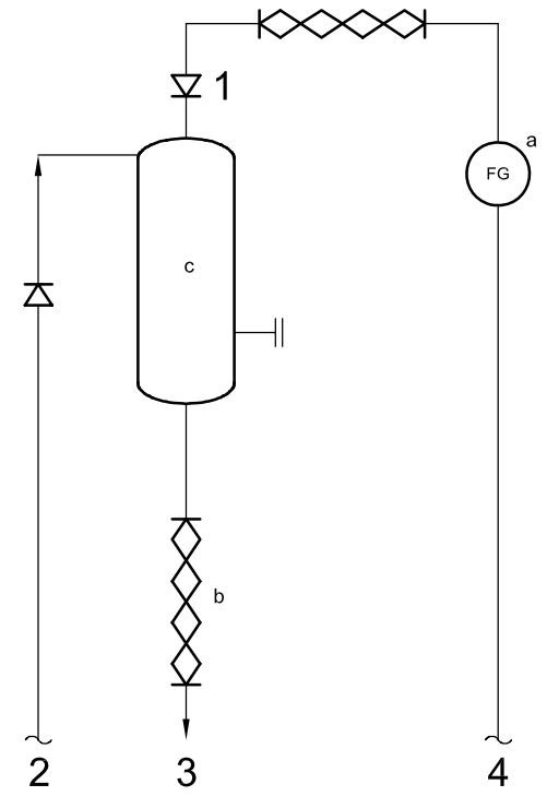
1 float-type check valve
2 lube-oil supply
3 to equipment
4 to reservoir or drain header
a Locate site glass near the reservoir in a visible location.
b To reduce pressure-ine losses, locate and design interconnecting piping as per system designer's recommendations.
c This tank shall be located at an elevation such that the static head is less than the equipment lube-oil trip pressure.
'Engineering > Mechanical Equipments' 카테고리의 다른 글
| Accumulator 사용상 주의사항 (0) | 2022.10.29 |
|---|---|
| Correctly Commission Rotating Equipment (0) | 2022.08.31 |
| Flange Flexible Couplings (0) | 2021.07.21 |
| Reciprocating Compressor Trouble Shooting (0) | 2021.07.21 |
| K.O. Drum (Knock Out Drum) (0) | 2015.04.30 |


